

 English
 عربى

Hole Edge Distance in Aluminum Windows and Curtain Walls: Practical Rules
Nov 09, 2026
Content
A hole drilled a few millimetres too close to the edge of an aluminum mullion can look perfectly acceptable on the bench and still fail the first time wind suction reverses the load on a facade. Hole edge distance is one of those details nobody discusses until something tears out, and by then the repair involves scaffolding, replacement profiles and a difficult conversation with the client.
We manufacture aluminum windows, doors, curtain walls, sunrooms and railings, and we have learned that edge distance is less about memorising a table than about understanding what the fastener is actually doing. Below we cover the definition, the values most specifications settle on, and the habits that keep connections sound in the workshop and on site.
What Hole Edge Distance Actually Means
Edge distance is the distance from the centre of a hole to the nearest edge of the material. It is measured from the centre, not from the rim, and that single detail accounts for a large share of the disagreements we see between fabricators and inspectors. A 12 mm hole with an 18 mm edge distance leaves only 12 mm of actual metal between the hole wall and the edge, which is a very different situation from the number printed on the drawing.
- Edge distance — from the centre of the hole to the nearest side edge, measured perpendicular to the direction of load.
- End distance — from the centre of the hole to the end of the part, measured parallel to the direction of load.
- Spacing or pitch — from the centre of one hole to the centre of the next.
The three dimensions work together. A connection with generous spacing but a thin edge fails by tear-out, where the fastener rips a wedge of material out of the profile. A connection with a thick edge but tight spacing can fail by block shear instead. Good detailing sizes these dimensions so the aluminum deforms gradually and visibly rather than fracturing without warning.
The Numbers Most Specifications Agree On
Codes phrase the requirement differently, but all of them scale minimum edge distance to fastener diameter. The figures below are the long-standing values that many detailing offices still carry over as a starting point.
| Fastener diameter | Sheared or cut edge | Rolled, formed or finished edge |
|---|---|---|
| 1/2 in (approx. M12) | 7/8 in | 3/4 in |
| 5/8 in | 1-1/8 in | 7/8 in |
| 3/4 in (approx. M20) | 1-1/4 in | 1 in |
| 7/8 in | 1-1/2 in | 1-1/8 in |
| 1 in | 1-3/4 in | 1-1/4 in |
Older versions of this table have since been replaced in steel design by provisions that relate edge distance to hole type and to a stress rule: where the stress at the hole does not exceed a quarter of the maximum design stress, the tabulated distance may be reduced by 1/8 in. That concession is not a target. In facade work we rarely apply it, because the stress distribution around a bolt in a thin extrusion is difficult to justify with confidence.
Screws, rivets and anchors follow different rules
The Aluminum Design Manual takes a simpler line for screws: the distance from the centre of a screw to an edge of the part should not be less than 1.5 times the nominal screw diameter. For rivets and bolts in aluminum, the familiar figures of two diameters minimum and four diameters maximum to an edge, with roughly three diameters centre-to-centre, still describe sound practice. Anchor bolts cast into concrete are a separate problem entirely — the governing dimension there is the distance from the anchor to the free face of the concrete, and it depends on embedment, anchor type and base material strength. A number borrowed from a steel table tells you very little about a concrete edge.
Why Aluminum Profiles Need Extra Care
Steel connections usually have enough material around the hole to spread bearing pressure. Aluminum facade profiles rarely do: a typical window profile wall is between 1.4 mm and 2.0 mm, so a 6 mm screw leaves very little metal to resist tear-out.
- Thin walls deform locally. Bearing stress peaks right at the hole edge and a thin wall can yield well before the connection reaches its design load.
- Load direction reverses. Wind suction pulls where pressure pushed, so the critical edge can change from one side of the hole to the other.
- Slotted holes are not free space. An oversized or slotted hole effectively moves the edge closer, which is why slot length has to be checked against end distance.
- Cut edges are the corrosion front line. Anodised and powder-coated surfaces stop at the cut, so a hole placed too close to the edge can leave a thin sliver of unprotected metal.
- Site drilling wanders. A hole intended at 20 mm from the edge can easily end up at 16 mm with a hand-held drill.
Where It Goes Wrong on Site
Most edge-distance problems we investigate are not design errors. They are small decisions made under time pressure.
- Measuring from the hole rim rather than from the hole centre.
- Drilling from the wrong reference face, so the hole creeps toward the edge.
- Reaming a hole to chase misalignment instead of moving the fixing.
- Driving self-drilling screws into a corner where two free edges meet.
- Mixing fastener sizes, so a screw sits in a hole drilled for a larger one.
- Applying the stress-based reduction without recording why it was justified.
A Practical Checklist Before You Drill
- Confirm fastener diameter, hole type and load direction before anything is marked.
- Punch and measure from the centre, and check the distance to the nearest edge rather than only the edge shown on the drawing.
- Treat 1.5 times diameter as the floor for screws, and 2D for rivets and bolts unless the project specification says otherwise.
- Check the corner first; where two edges meet, the effective edge distance is the smaller of the two.
- Drill and load a sample when the connection is safety-critical, rather than trusting a calculation alone.
- Record any deviation and get it approved when the geometry genuinely will not allow the minimum.
How We Handle It in Production
In our workshop, edge distance is controlled by tooling rather than memory. Mullion and transom connections are drilled on jigs and CNC centres with fixed datum stops, so the distance from the hole centre to the profile edge is set once and then repeated. Samples are checked before a batch runs, and positions that must be drilled on site are marked from the same datum used in fabrication, which keeps the tolerance budget honest.
This matters most on systems that carry concentrated loads. On our stick-built aluminum curtain wall, brackets transfer the dead load of the panels into the structure through a small number of bolts, and every one of those bolts depends on a predictable edge distance in the mullion behind it.
 Stick-Built Aluminum Curtain Wall SystemSite-assembled curtain wall with thermally broken aluminum mullions and transoms, relevant here for predictable mullion edge distances and bolted bracket connections.View Product →
Windows are a different exercise, because hinges, stays and handles sit close to the frame edge by necessity. The hole positions are set in the jig instead of being marked by hand, and the fixing screws are matched to the wall thickness of the profile. Installation tolerances in general, including how much movement a sliding sash needs, are covered in our guide to aluminum sliding window installation.
Railing posts deserve the same discipline. A base plate fixed with four anchors into a narrow mounting surface concentrates pull-out force on the two anchors nearest the free edge, so the plate layout and the anchor spacing are reviewed together before the posts are drilled.
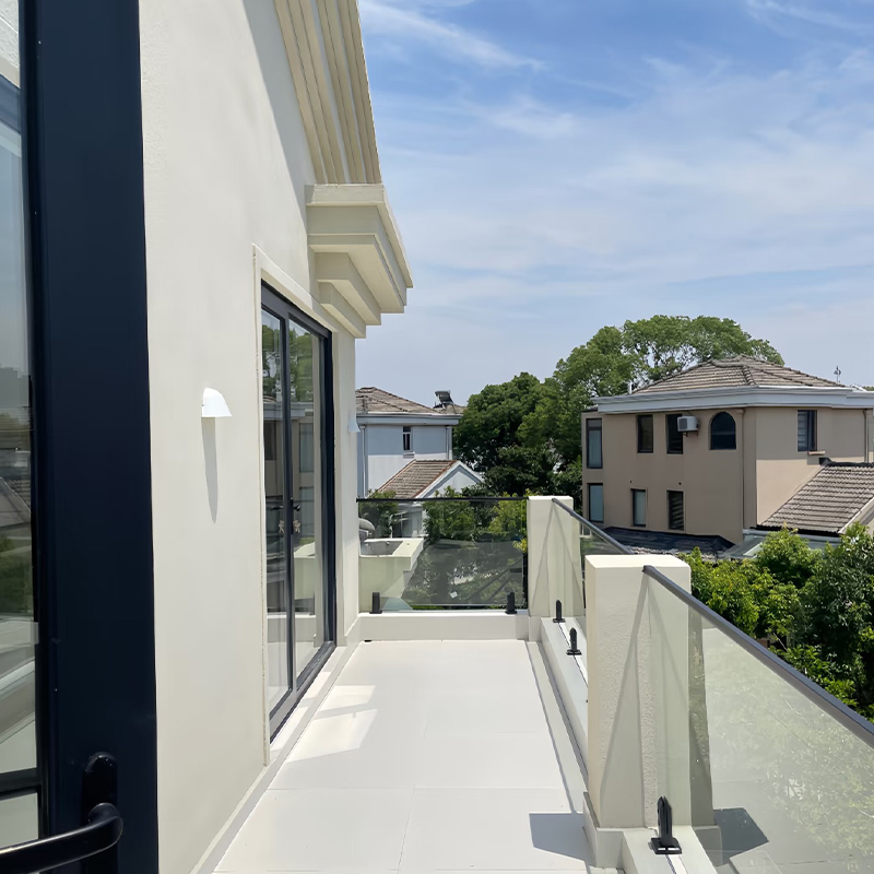 Aluminum-Framed Glass Balcony RailingAluminum-framed glass balcony railing with tempered laminated panels and clamp fittings, relevant when reviewing post base-plate layouts and anchor edge distances.View Product →
Edge distance is a small number with a large consequence. Getting it right costs a few minutes at the drilling jig; getting it wrong costs a call-back, a replacement panel and, occasionally, a safety review of the whole facade. Our teams have inspected project sites in the Philippines for exactly this kind of connection detail, and the lesson is always the same: decide the dimension before the drill bit touches the profile, and check it against the material in front of you rather than the drawing alone. If you are working through a connection that will not fit the minimum, our engineering team is happy to look at the geometry with you.



- Mobile
- Products
- Aluminum Window Series
- Aluminum Door Series
- Aluminum Sunroom Series
- Aluminum Sunroof Series
- Aluminum Louver Series
- Aluminum Railing Series
- Aluminum curtain wall
- Aluminum panel
- Aluminum door, window and curtain wall auxiliary materials
- Contact Us
-
-
+86-137 5720 8001

-
[email protected]

-
Room 102, Building 7, No. 399 Shushan Road, Hudong Street, Wuxing District, Huzhou City, Zhejiang Province, China

-



