

 English
  عربى
عربى 
Minimum Wall Thickness for Sand Casting Aluminum: A Practical Design Guide
Aug 19, 2026
Content
Your CAD model shows a neat aluminum bracket with a 2 mm wall, and the foundry quotes it at three times the expected price. The reason is simple: most sand casting shops treat 3 mm (about 0.120 in) as the practical minimum wall thickness for aluminum, and 4.8 mm (3/16 in) as the value they actually want to see on production parts. A 2 mm wall is not impossible, but it turns a routine casting into a sensitive one. Fill time becomes critical, the pouring temperature window narrows, and the reject rate climbs.
The conclusion before you send a print to a foundry: design to 3 mm for small, localized features such as ribs and bosses; target 4 to 5 mm for general walls and structural sections; and only push thinner when the part is small, simple, and the foundry confirms it can run the job. This article explains where the numbers come from, which design details raise the floor, and what defects follow if you ignore it.
The Numbers Behind the Rule of Thumb
Foundry guidance and design references cluster in the same range. Engineering design references commonly list a minimum of 2.5 mm (0.100 in) for aluminum webs and walls in sand casting. Production foundries typically quote 3.0 mm (0.120 in) as their standard minimum for general walls, with 3.8 mm (0.150 in) to 4.6 mm (0.180 in) recommended for dependable filling. Very small, isolated areas can run down to about 2.3 mm (0.090 in), while very large parts often need at least 6.4 mm (0.250 in) because the mold fill distance and solidification behavior change with scale.
No single number fits every job. The cited minimum is only a starting point; the practical limit depends on part geometry, alloy, sand media, gating design, and the foundry's process controls. Use the table below as a reference, then confirm with the specific foundry that will quote your part.
| Feature or part size | Minimum for production | Recommended design target |
|---|---|---|
| Small localized features (ribs, bosses) | 2.5–3.0 mm (0.100–0.120 in) | 3.0 mm (0.120 in) |
| General walls on parts under 300 mm | 3.0 mm (0.120 in) | 4.0–5.0 mm (0.160–0.200 in) |
| Large or structural walls over 300 mm | 4.0–5.0 mm (0.160–0.200 in) | 5.0–6.0 mm (0.200–0.240 in) |
| Complex thin webs in cored sections | 3.0–4.0 mm (0.120–0.160 in) | 5.0 mm (0.200 in) |
Why Aluminum Sand Casting Has a Thickness Floor
Molten aluminum at typical pouring temperatures between 680 and 760 °C is fluid, but not infinitely so. In a sand mold, the metal must travel through the gating system and fill the entire cavity before the leading edge freezes. Thin sections increase the surface-to-volume ratio, which accelerates freezing and drains heat from the melt. When the flow front cools below a critical temperature, it stops moving.
Three process variables set the real floor on wall thickness:
- Metal fluidity: a higher pouring temperature improves fill capability but increases gas pickup and oxidation, so foundries limit how far they can push it.
- Mold media: green sand is economical but has lower strength and permeability. No-bake (chemically bonded) sand is more rigid, permits slightly thinner sections, and is preferred for better surface finish and dimensional control.
- Feeding and solidification: a thin wall freezes quickly, while a thicker adjacent section remains liquid longer and can draw feed metal from it, creating shrinkage porosity in both areas.
Design Details That Raise the Practical Minimum
Even when a wall itself is above 3 mm, standard foundry design rules can reduce the effective wall thickness or create conditions that make thin sections fail. These are the details that most often push the design minimum upward.
Draft Angles
Every vertical surface needs a draft angle so the pattern can be withdrawn from the sand. A 1 to 2 degree angle on external walls and 2 to 3 degrees on internal walls is typical. Over a wall height of 50 mm, a 2 degree draft removes roughly 1.7 mm from one end of the nominal thickness. If you start at 3 mm, one end of the wall drops toward 2 mm, which is below the practical floor.
Corner Radii
Sharp internal corners are both stress concentrators and hot spots where shrinkage porosity forms. Generous radii also help sand flow during mold making. As a rule, use an inside radius at least equal to the local wall thickness; a ratio of 1.5 times wall thickness is even safer.
Section Transitions
Abrupt changes from thick to thin sections are common sources of misruns and hot tears. Keep wall thickness as uniform as possible. When a change is unavoidable, transition gradually with a taper or radius, keeping the ratio between adjacent sections at or below 3:1.
Bosses, Ribs, and Web Junctions
Bosses create heavy isolated masses that need feed metal after the surrounding thin walls have frozen. Ribs should be thinner than the walls they support, traditionally 60 to 80 percent of the adjacent wall thickness, so the rib solidifies first and the heavier wall can feed it. A junction of two walls at a rib creates a local mass concentration; add a radius and keep the rib thickness below the main wall to avoid porosity.
Defects That Appear When Walls Are Too Thin
Designing below the minimum does not simply make a casting harder to produce; it produces recognizable defects that add scrap cost and delay delivery.
- Misruns and cold shuts: the melt freezes before the cavity fills, leaving incomplete edges or visible flow lines. This is the most common failure with thin aluminum walls.
- Gas porosity: thin sections trap gas as the metal freezes; aluminum also absorbs hydrogen in the molten state, and the small feeding paths in thin walls cannot push the gas out.
- Hot tearing: when a thin wall cools and contracts faster than a connected heavy section, the restrained area can tear at the junction, especially at sharp transitions.
All three defects share one trait: they are sporadic. A thin wall can run fine in a trial batch, then fail intermittently in production as pouring temperature, sand moisture, or ambient conditions drift. That is why foundries quote higher prices for sub-minimum walls.
Tolerances, Machining Allowance, and Shrinkage
Wall thickness is not the only dimension worth validating. Sand casting tolerances and shrink behavior directly affect whether a part, including its thinnest sections, stays within specification.
- Dimensional tolerances: for parts up to roughly 300 mm, linear dimensions often range from ±0.5 to ±1.5 mm depending on the feature and the mold media. Thin walls will shift within that envelope, so do not design a wall to the absolute minimum if the tolerance on the final part matters.
- Machining allowance: if a face will be machined, leave 1.5 to 2.5 mm of stock. Check that the wall thickness after machining remains above the foundry's minimum; otherwise, the casting has no practical chance of meeting the drawing.
- Shrinkage allowance: aluminum solidification shrinkage is roughly 1.3 percent (about 5/32 in per foot). Pattern makers compensate for this, but if you inherit an existing pattern, verify that the final wall thickness after shrinkage compensation still meets the design target.
Applying the Same Thickness Discipline to Aluminum Building Systems
The same mindset that makes a good sand casting design also makes a good aluminum building product. A sunroom frame with undersized wall thickness deflects under snow loads; a curtain wall mullion with too little section thickness fails wind-load calculations; a window sill with thin walls invites condensation and drainage problems. Buyers and architects rarely ask about minimum wall thickness when ordering windows, but the question deserves the same attention they would give a casting print.
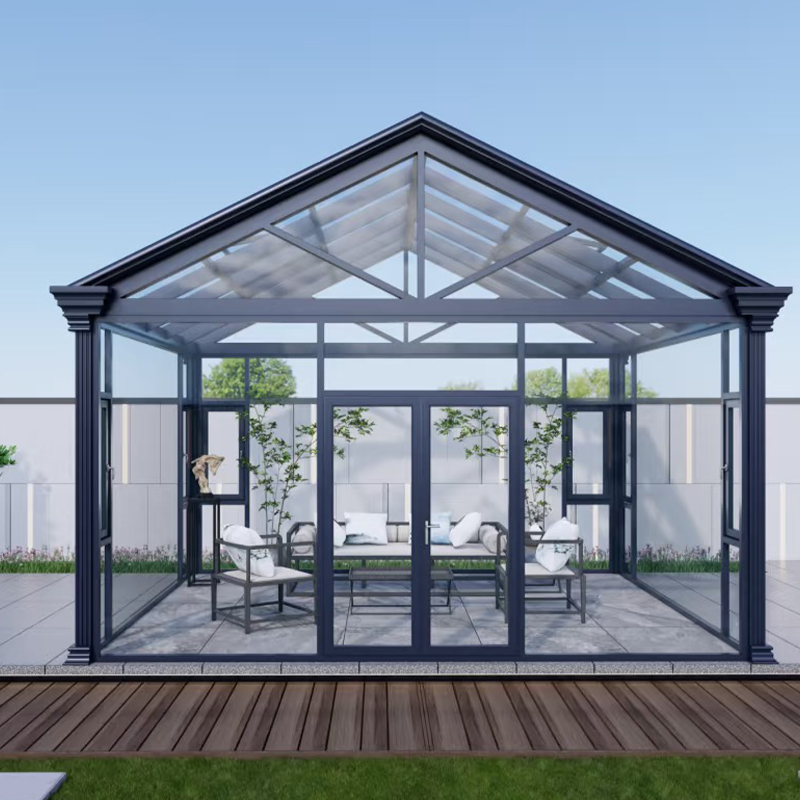
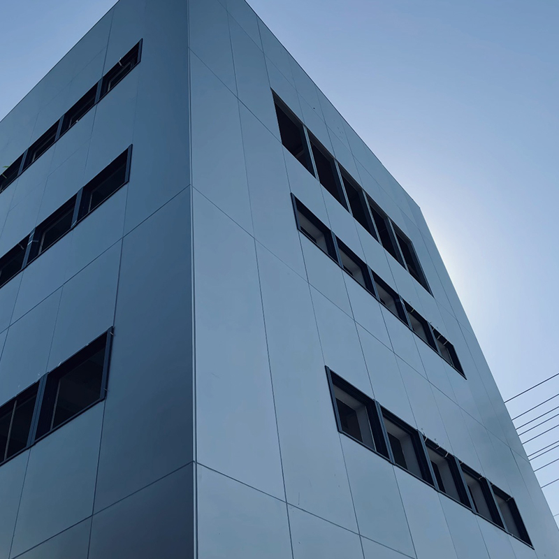
Dongcheng designs and manufactures aluminum windows, doors, sunrooms, railings, and curtain walls with section thickness chosen from structural calculations, not material-saving guesses. Production follows ISO9000 quality management procedures, so profile thickness, surface treatment, and assembly are standardized. The A-frame sunroom system with fast-drainage design, for instance, uses an optimized roof geometry with structural profiles sized for local snow and wind loads. The stick-built aluminum curtain wall, in turn, relies on mullions and transoms whose wall thickness accounts for wind load, seismic movement, and thermal expansion. The same logic applies to aluminum sliding windows, where profile wall thickness affects air tightness, water resistance, and long-term durability.
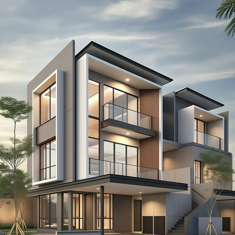 Wholesale Aluminum Stick-Built Curtain Wall Suppliers, Company - Zhejiang DongchDongcheng is Wholesale Aluminum Stick-Built Curtain Wall Suppliers and Company in China, Stick-Built Aluminum Curtain Wall, also known a...View Product →
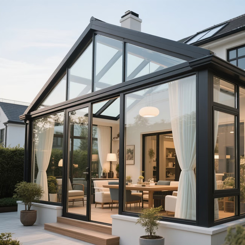 Wholesale Aluminum A-Frame Sunroom (Fast Drainage Design) Suppliers, Company - ZDongcheng is Wholesale Aluminum A-Frame Sunroom (Fast Drainage Design) Suppliers and Company in China, The A-frame sunroom features a sym...View Product →
When you source aluminum systems, use the same approach you would with a foundry: ask for section drawings, ask for the wall thickness and alloy temper of every structural profile, and request test reports for wind load, water tightness, and thermal performance. A supplier that answers clearly is the one you can trust.

- Mobile
- Products
- Aluminum Window Series
- Aluminum Door Series
- Aluminum Sunroom Series
- Aluminum Sunroof Series
- Aluminum Louver Series
- Aluminum Railing Series
- Aluminum curtain wall
- Aluminum panel
- Aluminum door, window and curtain wall auxiliary materials
- Contact Us
-
-
+86-137 5720 8001

-
[email protected]

-
Room 102, Building 7, No. 399 Shushan Road, Hudong Street, Wuxing District, Huzhou City, Zhejiang Province, China

-



