

 English
 عربى

How to Select ANSI/ISO Inserts for Turning Aluminum: A Practical Guide
Sep 08, 2026
Content
Your lathe is set up for a morning run of 6061-T6 aluminum fittings, and the drawing calls for a 0.8 µm Ra surface finish. The insert still sitting in the holder worked fine on last week's steel job, and it will let you down today. Aluminum is soft, sticky, and prone to welding onto the cutting edge, so a geometry designed for steel produces torn surfaces, built-up edge, and wasted material. The answer is to select an insert made for non-ferrous turning, and the ANSI/ISO designation system gives you the exact vocabulary to do that with confidence.
How to Read ANSI/ISO Insert Designations
The ISO 1832 designation system, adopted in North America as ANSI B212.4, describes an insert's shape, clearance angle, tolerance, and dimensions in a compact string of letters and numbers. The first character defines the shape, the second the clearance angle, the third the tolerance class, the fourth the chipbreaker and hole style, and the fifth through seventh characters define the inscribed circle, thickness, and nose radius.
| Position | What it defines | Aluminum-friendly value |
|---|---|---|
| 1 | Insert shape | C (80° diamond), D (55° diamond), T (60° triangle) |
| 2 | Clearance angle | C (7°) |
| 3 | Tolerance | G (ground sides) |
| 4 | Hole and chipbreaker | T (countersunk hole), aluminum-specific chipbreaker |
| 5 | Inscribed circle size | Common sizes: 09 (9.52 mm), 12 (12.7 mm) |
For aluminum, the third position matters more than most machinists expect. A G-tolerance insert is ground on every side, giving a sharp and consistent cutting edge. Molded inserts with an M or U tolerance have a stronger but duller edge intended for steel and cast iron. On aluminum, a molded edge pushes the material, generates heat, and creates built-up edge. Ground inserts cost slightly more, but they are the difference between a clean 0.4 µm finish and a torn 3.2 µm surface.
Why Aluminum Turning Demands Different Geometry
Aluminum's low melting point, high ductility, and tendency to cold-weld make it one of the most forgiving and yet frustrating materials to turn. The forgiving part is speed: aluminum can be cut at 400 to 600 m/min with uncoated carbide, far above typical steel speeds, and the cutting forces stay low. The frustrating part is built-up edge. At low speeds or with a dull edge, aluminum welds to the insert. The weld grows, and the next pass tears the surface of the workpiece.
A positive rake angle changes the mechanics of the cut. Positive rake geometry shears the soft aluminum away instead of plowing it, reducing cutting force and heat. This is why the most reliable aluminum inserts carry positive geometry: CCGT, DCGT, and TCGT all rely on ground edges with high positive rake. The polished rake face is just as important. A mirror-smooth top surface reduces friction, breaks adhesion, and keeps the cutting zone clean.
Selecting the Right Insert Geometry
Four geometries cover nearly every aluminum turning operation. The choice depends on the shape of the part feature you need to reach and the strength required in the cutting edge.
| Insert type | Angle | Typical use |
|---|---|---|
| CCGT | 80° diamond | All-round turning, shallow cuts, good edge strength |
| DCGT | 55° diamond | Finishing, small diameters, threading |
| TCGT | 60° triangle | General turning, higher feed rates, heavier stock removal |
| VBGT | 35° diamond | Copy turning, narrow grooves, hard-to-reach features |
Start with a CCGT or TCGT geometry for general work. The C-shape balances edge strength and workpiece access, while the T-shape is stronger and accepts a heavier feed. For finishing, a DCGT with a small nose radius around 0.2 mm cuts a cleaner profile with less vibration. Whatever shape you select, confirm that the insert has a G tolerance, a polished rake face, and a chipbreaker designed for aluminum if the supplier offers one.
Speeds, Feeds, and Cutting Practice
Aluminum's machinability allows aggressive parameters, but the insert geometry still sets the boundary. With uncoated carbide and flood coolant, a 6061-T6 bar can run at 450 to 600 m/min cutting speed, 0.15 to 0.25 mm/rev feed, and 1 to 3 mm depth of cut for roughing. For finishing, raise the speed to 600 to 800 m/min, drop the feed to 0.05 to 0.10 mm/rev, and use a depth of 0.2 to 0.5 mm.
| Operation | Speed (m/min) | Feed (mm/rev) | Depth of cut (mm) | Expected Ra (µm) |
|---|---|---|---|---|
| Roughing | 450–600 | 0.15–0.25 | 1.0–3.0 | 1.6–3.2 |
| Finishing | 600–800 | 0.05–0.10 | 0.2–0.5 | 0.4–0.8 |
| PCD finishing | 800–1500 | 0.05–0.15 | 0.2–1.0 | 0.2–0.4 |
Use generous flood coolant with a lubricity-enhancing additive if the machine has it; an 8 to 10% semi-synthetic concentration works well. When flood coolant is not available, air blast keeps chips from recutting. Dry cutting aluminum is possible at high speeds, but a polished rake face is essential to prevent adhesion. Keep the cutting speed above 250 m/min whenever possible; below that, built-up edge returns even with good geometry.
How Insert Quality Shows Up in Finished Products
The link between a well-chosen insert and a quality finished part comes down to surface integrity, dimensional stability, and repeatability. A turned aluminum part with a rough or smeared surface tells you the cutting edge is failing, and once the edge fails, dimensional drift follows. If that part must mate with others, a hinge pin in its bore or a lock mechanism in its housing, the result shows up as binding, leaks, or premature wear.
In building products, these small parts make the large assemblies work. The smooth operation of a sliding window depends on rollers and locking components machined to tight tolerances; poor finish here means a window that rattles or refuses to glide.
 Left-Right Sliding Aluminum Window with Dual-Track RollersThis sliding window uses precision-machined rollers and multi-point locks, directly addressing the article's point about small parts determining smooth operation. Its dual-track stainless steel system and EPDM seals promise reliable, low-maintenance performance.View Product →
Casement doors are no different. Their pivot hinges and multi-point locks include turned components, and the difference between a door that closes with a soft click and one that has to be forced is determined by the finish and tolerance of those parts.
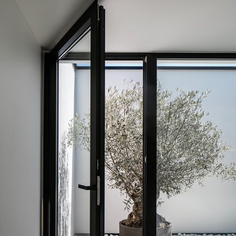 Aluminum Casement Door with Multi-Point Locking HardwareThe casement door's heavy-duty hinges and multi-point locks highlight the importance of turned component tolerance, as noted in the preceding paragraph. It offers secure, rattle-free closure with continuous EPDM gaskets for insulation and weatherproofing.View Product →
Unitized curtain wall systems depend on machined connectors, brackets, and fasteners assembled to tight nominal dimensions. One out-of-tolerance turned part can leave a panel sitting proud by a millimetre and create an air or water leak path across the facade.
 Unitized Aluminum Curtain Wall for High-Rise FacadesThis factory-assembled curtain wall system relies on precisely machined connectors and brackets, matching the article's discussion of tolerance in facade assemblies. Its unitized construction speeds installation and ensures consistent sealing across large projects.View Product →
With thousands of such components required per project, even a 1% scrap rate becomes a costly problem. That is why machine shops that supply the aluminum window and door industry switch to dedicated aluminum inserts instead of making do with steel tooling. The same discipline applies to anyone turning aluminum in-house: read the ANSI/ISO code, load a ground and polished positive-rake insert, and verify the surface finish at the start of the batch. If you see smearing, fix the tool before adjusting the speed. Anyone specifying window systems will find related guidance in our sliding window buying and installation guide.
A Simple Insert Buying Checklist
When you open a tooling catalogue, keep this list in front of you:
- Confirm the shape, inscribed circle size, and thickness match the holder pocket.
- Require a G tolerance class for a ground, sharp cutting edge.
- Look for a polished rake face; skip coated steel-oriented inserts.
- Choose positive rake geometry and run the speed above 250 m/min.
- Test one insert on an actual part before buying a large box.
The ANSI/ISO code tells you exactly what is in the box. A few minutes of verification at the machine tells you whether that specification fits your application. For turning aluminum, sharp, polished, positive-rake inserts are non-negotiable; everything else is a variable you can adjust.



- Mobile
- Products
- Aluminum Window Series
- Aluminum Door Series
- Aluminum Sunroom Series
- Aluminum Sunroof Series
- Aluminum Louver Series
- Aluminum Railing Series
- Aluminum curtain wall
- Aluminum panel
- Aluminum door, window and curtain wall auxiliary materials
- Contact Us
-
-
+86-137 5720 8001

-
[email protected]

-
Room 102, Building 7, No. 399 Shushan Road, Hudong Street, Wuxing District, Huzhou City, Zhejiang Province, China

-



